A guide to synchronisation in data centres
What data centre architects and other networking specialists need to know about 5G synchronisation
With the roll-out of 5G, a massive shift is happening in how telecom infrastructure is designed. With network operators wanting to create a more open network infrastructure ecosystem, part of the infrastructure, such as baseband processing, is virtualised and moved into telecom data centres. Another 5G-related trend that affects data centre architecture is Mobile Edge Computing, which enables very low latency and benefits from a more distributed infrastructure such as local cloud centres that are part of the RAN.
How does the 5G revolution affect data centre architecture?
The majority of IT data centres today typically provide computer storage and processing functions for various applications. Synchronisation between centres is necessary to manage databases, optimise search functions, deliver real-time content and provide faster responses to users. To enable the applications to perform the required functions, the accuracy of synchronisation needed between data centres is in the order of milliseconds. The critical requirement is the reliability of data delivery, not necessarily delivering this data within a specific time. This means that although synchronisation is important, it is not yet mission-critical.
When it comes to 5G however, synchronisation is essential to the operation and network performance. Traditionally base stations acquire timing from GNSS or backhaul networks and synchronise the radios. With data centres taking on the roles of base stations, data centres should be equipped to serve synchronisation to the radios. For 5G, the accuracy requirements are much more stringent than for previous generation networks. The ultra-reliable low-latency communication networks that offer autonomous driving and enable Industry 4.0 require extremely accurate synchronisation, with the accuracy of synchronisation between radio elements connected by data centres needing to be in the order of 100s of nanoseconds to enable the applications to perform required functions. So when data centres become part of 5G networks, incorporating telecom grade synchronisation features into the data centres becomes critical in building a superior network.
What are the synchronisation requirements for data centres?
As we have seen above, 5G and Mobile Edge Computing are increasing the need for distributed data centres in the RAN, but also traditional data centres now require more accurate timing and synchronisation. The industry is quickly catching on to these trends, with several initiatives providing guidance and setting standards and protocols.
Here are the most important ones you need to know about.
Given the increased need to provide a higher level of accuracy for various applications, the Open Compute Project is now building a DC (Data Centre) Profile for PTP (IEEE 1588 Precision Timing Protocol)1. This profile stipulates a reference model of synchronisation and target accuracies for data centres (see Timing Appliances Project HRM below). The profile will apply to time-sensitive applications over OCP-compliant and PTP-aware networking infrastructure such as network switches, equipment clocks, network interface cards, & timing modules, etc.
The following diagram from the Timing Appliances project group presents an overview of data centre synchronisation reference models and error budgets. In this diagram, the data centre may host an edge Grand Master (DC-GM), which acts as the master clock. The Spine Switches (SSW) and the Fabric Switches (FSW) typically deploy Transparent Clocking, whereas the Rack Switches (RSW) deploy boundary clocks. The servers themselves are recommended with End Node Ordinary Clock deployments. The overall error budget is proposed to be within 5us.
Fig 1. Hierarchical Reference Model (HRM) and proposed error budgets
In addition, the increasing importance of Time Sensitive Network applications has prompted the IEEE to create the IEEE802.1AS-2020 standard, defining the requirements of Timing Synchronisation for TSN networks2. 5G can be regarded as a TSN bridge in the overall TSN network architecture and can provide communication and synchronisation services for various use cases.
The following figure gives an overview of how the 5G network would connect two systems that need to work with TSN networks.
Fig. 2. 5G system fitting into TSN networks
The O-RAN Alliance has been working on deployment and synchronisation scenarios of 5G networks3. Of all the common applications seen, 5G presents the most stringent synchronisation requirements, bringing the radio synchronisation to 130 nanoseconds4. The Time Alignment Error (TAE) is split between the baseband processing unit and the end radio application. All the equipment involved in building the 5G network add to this error, and depending on the function and location of the equipment, the timing budget allowed is determined. For data centres, Timing Grand Masters, Server DU equipment are likely involved, as well as the switching fabric that connects various elements.
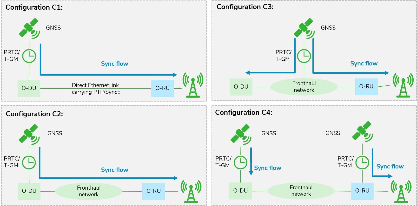
The synchronisation deployment scenarios defined by O-RAN are captured on the following diagrams. C1 is the scenario when the DU and the RRU are directly connected. With C2, there can be a fronthaul network of switches for the traffic distribution, which might increase the complexity of synchronisation. The C3 diagram assumes that the synchronisation originates in the network and is distributed to both the DU and RRUs. Lastly, C4 show that the DU and RRU can be independently synchronised.
To support each of the synchronisation scenarios, the data centres must be equipped with adequate architectures.
Fig. 3. ORAN Synchronisation deployment scenarios (Calnex)
The synchronisation performance in transport networks is guided by the SG15-Q13 ( ITU-T)5. Here the datacentre elements become part of the network by becoming one or more of the following elements: a CU/DU function, Time Grand Master or Switching / Routing elements.
Timing Grand Masters should follow the recommendations outlined in the ITU standards G.8272/G.8272.1.
For CU/DU equipment and for switching and routing elements, synchronisation - implemented either on-board or as a network interface card - may need to satisfy some or all of the mobile synchronisation standards of requirements:
- ITU – T G.8273.4, Assisted And partial timing support clocks
- ITU – T G.8273.2, Telecom boundary clocks
- ITU – T G.8262, G.8262.1 Ethernet Equipment Clocks (EEC) and enhanced EEC
On top of this, one key element that is expected on the front haul elements is holdover. Holdover is the ability to perform synchronisation functions within certain limits for a certain time to support the service level agreements of the telecom. Search requirements add further design complexities into the synchronisation architecture.
Network synchronisation may deploy a number of synchronisation sources. The primary source of synchronisation needs to be close to atomic sources, and the commonly available source is GNSS based systems.
Other sources are packet-based synchronisation methods, such as PTP (IEEE1588) and physical layer synchronisation (such as Synchronous Ethernet). A local oscillator, stable enough to be steered, is the heart of the synchronisation system.
Fig. 4. A typical synchronisation system implementation for 5G element
The 5G requirements stipulate a 50ppb frequency accuracy across all radios in the network and +/-130ns accuracy across the RRUs of the same DU. The network clock must be filtered with a bandwidth that is low enough for the output clock to meet 50ppb measured in 1ms intervals. GNSS interfaces typically use a 1PPS interface into the servo system, which necessitates a bandwidth of 10s mHz. The fronthaul suggested by O-RAN requires support for G.8275.2-like profiles. G.8275.2 profile and corresponding G.8273.4 clock do not have synchronisation support from the physical layer network and thus demand sub mHz filtering bandwidths.
The G.8273.2-like clocks require a minimum bandwidth of 50mHz. The above criteria demand low bandwidth servos in synchronisation implementations, which results in the need for high stability reference clocks in the system to minimise the Time Alignment Error across the operating temperature range. Combined with the holdover requirements, selecting reference clock oscillators becomes key in the architecture and design of synchronisation systems.
GNSS Signal jamming
In most cases, the primary source of synchronisation is from global navigation satellite systems. Since the signals are omnipresent, it is relatively simple to achieve synchronisation, as long as the antennas have a direct line of sight of the sky. The ready availability of GNSS systems makes them ubiquitous in many applications such as vehicle tracking and fleet management. However, jamming of GNSS systems is also very common, intentionally or otherwise. For example, drivers who may want to go off the tracking grid may use various jamming techniques. In the process of making GNSS signals unavailable to their tracking devices, the jamming devices also disrupt nearby communications systems that use GNSS to recover synchronisation. Any jamming can last for hours, and alternative synchronisation mechanisms need to be in place to mitigate network outages due to synchronisation failures. Backup systems are required to assist synchronisation in holding the requirements through PTP, Synchronous Ethernet or Oscillators. The fundamental alternative is to have high stability oscillators providing synchronisation continuity through a holdover mechanism.
Profile / Performance trade-off
For NIC card-based synchronisation architectures, the distance between two PICe cards is 20.32mm. According to the OCP NIC3.0 specifications, the component side of the PCB can have a maximum height of 11.5mm. Finding a high-performing oscillator device to fit this form factor is exceptionally challenging, especially when the system requires a holdover performance. For on-board synchronisation topologies, the server designs are dense and complex so that the form factor of a component needs to be the smallest possible, delivering a certain level of performance.
Harsh environments – High airflow, shock and vibration
Data centre environments are relatively controlled in terms of the impact of temperature variations. However, most server systems have an increased amount of airflow and sometimes higher levels of shock and vibration. The synchronisation systems should be able to handle such harsh environments.
Support for a superset of features
To allow for possible future applications with more stringent requirements, equipment needs to be future-proofed as much as possible. This is where we need to consider the trade-offs between features, standards compliance and cost.
Superior resonator technologies, innovations on ASIC-based TCXO and OCXOs’ advanced electro-mechanical designs make it possible to develop products that address these new challenges and produce cost-effective solutions.
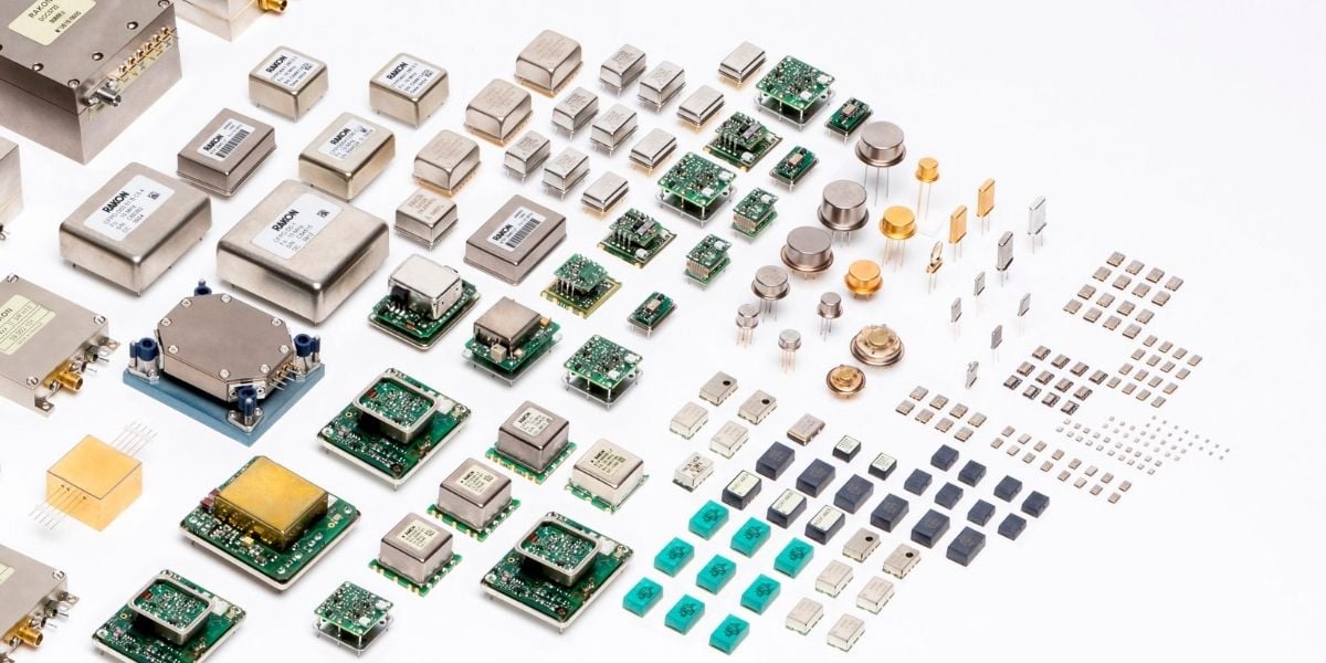
Quartz based oscillator technologies are best known for their availability, reliability, performance and proven long-life performance for the lifetime of the equipment. New technology innovations such as Rakon’s XMEMS technology, advancement in the fundamental vaccinator development, innovation in ASIC-based control circuitries, advanced thermal-mechanical packaging techniques - have all enabled the production of 7 mm x 5 mm oscillators with stratum 3E-like stability capabilities, which are resilient to several CFM‘s of airflow as well as withstanding less than 0.5pppb/g like impacts.
Holdover is vital in supporting the system when the synchronisation source becomes temporarily unavailable due to GNSS jamming, spoofing or other reasons. 5G system requirements for 4+ hours, up to 24 hours are becoming increasingly common.
As fifth-generation mobile networks become a reality and time-sensitive networks are growing in number and importance, data centres require much higher accuracy of timing and synchronisation than in the past. It is essential to prioritise synchronisation and plan for a superset of features to future-proof data centre equipment.
Would you like more content like this delivered to your inbox?
Subscribe to our emails now!
Related content

White Paper: Synchronisation requirements in URLLC networks
5G technology has a focus area known as Ultra-Reliable Low-Latency Communication (URLLC). This technology provides ultra-high reliability and low...

Blog: What is synchronisation holdover, and why is it important in future-proofing telecom networks?
Holdover is a technique used in telecommunications to maintain accurate timing and synchronisation of equipment in the event of a temporary loss of...

Blog: Synchronisation fundamentals for digital communication systems
Synchronisation is fundamental to most coordinated activities, from a performance by a symphony orchestra or ballet company to digital...
Want to know more about our products?
Browse our product pages.
Find products using our parametric search
Talk to our sales engineers


