E-BOOK

System-level synchronisation reference compensation for extending time holdover

Phase and time synchronisation have become the fundamental requirements of most telecom and data communications networks today, as numerous end applications use precision timing. Whether consumer, business or industrial applications, the enabling technology requires synchronisation to achieve functionality and performance.

To provide the throughput of 5G, features such as carrier aggregation require stringent phase alignment. Likewise, keeping the air interface of radios within +/-130ns of the same base station is demanding, even when synchronisation sources are available.

Applications that rely on URLLC (Ultra-Reliable Low Latency Communication) – which enables 99.999% availability of services – need very reliable synchronisation in all possible scenarios. Time Sensitive Networks (TSN) such as industrial, financial and automotive networks, data centres, power grids and 5G Virtual RAN deployments, all require high precision synchronisation.

Look beyond standards bodies’ recommendations

The standards bodies provide hierarchical reference models and deployment scenarios for synchronisation. However, actual deployments depend on many circumstances that may not be factored into the standards. For example, for mobile operators, interoperability and co-existence with current networks are critical. Operators generally try to re-use the existing network rather than deploying a new network for new technologies. In such scenarios, the traditional synchronisation mechanism may not work, and atomic clocks tend to be ‘parachuted’ onto the edge nodes of the networks.

Synchronisation is critical but can easily be interrupted

In general, synchronisation systems are created on a hierarchical level. A master clock acquires data from an atomic clock and distributes the data in a master-slave or mutual synchronisation mechanism across the network. The most common way to get reference timing into a network is through GNSS-based, readily available technologies. GNSS-based synchronisation is the easiest way to bring the highest quality timing into any system. However, the GNSS’ very low signal levels also bring about the system’s vulnerability.

GNSS signals only need very low receiver sensitivity, which means they are prone to jamming. Many applications today use GNSS tracking, and not every end-user is happy with that. Some people will go to great lengths to not have their location tracked. They may remain invisible from GNSS-based tracking by jamming already weak signals with a low-cost jammer. Such devices are illegal in many countries. The jammer device will do its job by making the user’s location disappear from the tracking system. However, unintentionally, the jammer also affects the nearby GNSS receivers used in telecommunication systems. If not appropriately engineered, this may bring down the synchronisation mechanisms and possibly the network operation itself.

In addition to signal jamming, signal loss can also be caused by barriers such as physical antenna failures, solar activities, urban canyons atmospheric disturbance or weather conditions.

What is holdover and how does it mitigate the loss of GNSS signals?

Assisted clocks refer to the capability of clocks to have traceable, precision timing-based network synchronisation to support GNSS-based clocking. When the GNSS signals become unavailable for any reason, the clocking support from the network takes over. The state-of-the-art network synchronisation method is based mainly on Precision Time Protocol (PTP) which is supported by physical layer timing. In situations where the network synchronisation is unavailable, the system falls back to the system’s reference clock. The ability of the system to hold the clocking error within certain variation limits for a certain period is called ‘holdover’. 

Holding the frequency error within the limits required by most of the applications previously discussed is possible with cost-effective reference clocks. However, when it comes to limiting the ‘phase’ or ‘time’ error within the limits of the applications’ requirements, this becomes expensive with the class of reference clock oscillators that are typically used in such systems. This e-book explores the techniques available to compensate the reference clocks on a system level, to provide a long-term ‘time holdover’ performance.

Want to calculate holdover for your chosen oscillator? Try our new holdover simulator app now!
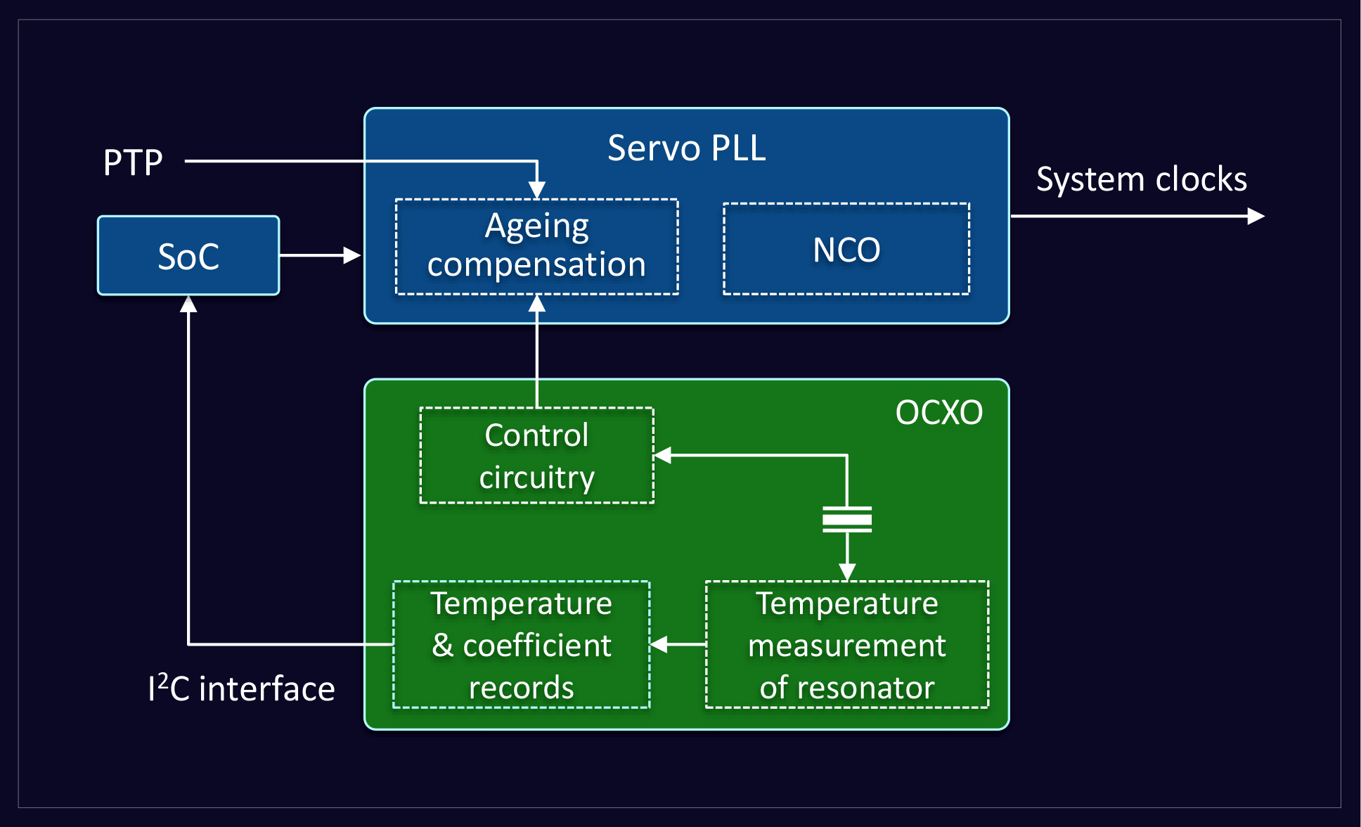
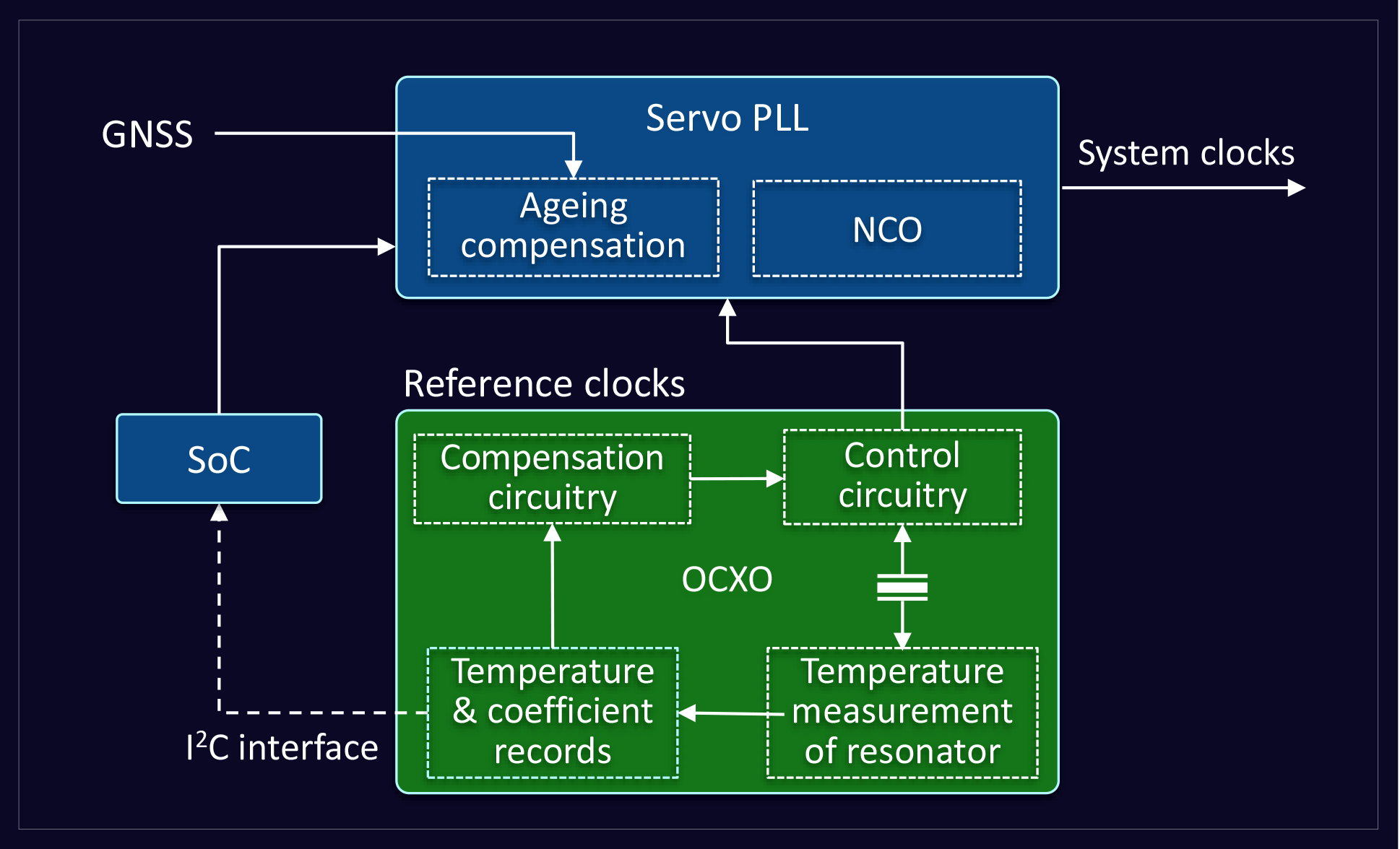
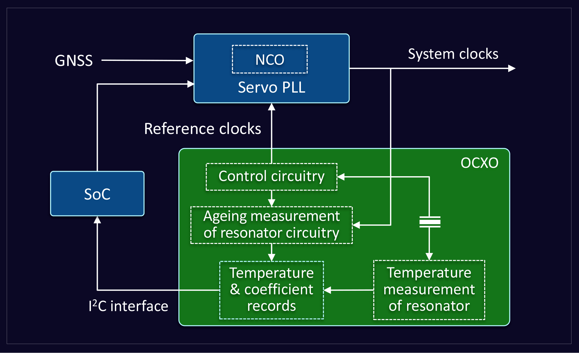
Synchronisation scenarios: basic synchronisation system

The illustration here is a generic implementation of a synchronisation system. The GNSS-based clocking synchronisation is the primary reference clock, and in the event of GNSS signal loss, the PTP based clocks take over. PTP based ’holdover’ can provide phase as well as frequency corrections. There is one additional layer of protection even when the PTP based clock failure supports physical layer clocks. Such clocks can only do frequency synchronisation and are capable of holding the phase. Finally, the fundamental and default holdover comes from the reference clock of the system.

Holdover of servo systems is mainly affected by the following issues

  1. Servo initial error: Holdover may occur at any instant of operation of the servo system. At that instant, the error of the system is caused by the initial phase error and frequency accuracy of the servo.
  2. Frequency deviation due to temperature variation: Temperature variation is the fundamental short-term impact on oscillators. Higher frequency stability ensures minimal phase movement.
  3. Ageing drift: The fundamental building block of the oscillator is a resonance element that builds up the fundamental oscillator. Ageing is the systematic variation that happens to the resonator over time by materials being deposited on the quartz crystal or materials being vaporised from it. This results in slow variation in frequency and long-term deviation in phase movement. Ageing is presented in parts per billion per day (ppb/day) variation.
  4. Hysteresis and other system effects: The frequency difference that the resonator accumulates over temperature cycles is called the hysteresis effect. The re-trace impact is the difference in frequency an oscillator exhibits when it undergoes a power cycle. Power supply variations and load variations also cause the frequency to deviate.
  5. Random variations: Due to the nature of the resonator, frequency drift can be caused by random effects, primarily measured in the Allan Deviation metric.


The servo initial error is mainly controlled by the servo design. The hysteresis, re-trace, power supply variations and the random variations are related to the resonator characteristic and the basic circuitry design. Of all the different types of contributors to the changes in reference clock frequency, the major contributors are variations in temperature and drift due to ageing. A system trying to achieve short to medium term holdover (4–8 hours) will have a significant impact (90% variation) from these two factors. Therefore, the system designers have been engaging various techniques to improve the holdover performance by addressing these two specific issues. Temperature variation and ageing drift are variations that can be dynamically addressed in the systems. There are a number of methods that can be used to compensate the synchronisation reference caused by temperature variation and ageing.

Temperature post compensation using external temperature sensors

Depending on how Oven Controlled Oscillators (OCXOs) are manufactured, individual oscillators can show different residual effects that are entirely independent of each other, even across different samples of the same family of products. The uncertain response is because the OCXO building mechanism mostly tries to fit the minimum or minimal slopes of the resonance characteristics. Initially, to compensate for temperature variations, each oscillator is inserted into the equipment with temperature sensors around it, to map the behaviour across temperatures

These characteristics are then used to compensate for the temperature variation. Such proprietary techniques used to cause major infrastructure, logistics, and economic costs to system designers. The characterised data from individual oscillators are used in the system to compensate for temperature effects. In parallel, systems use network-recovered reference clocks to measure oscillator variations to compensate for the ageing effect.

Temperature post compensation using embedded coefficients

In the next generation of synchronisation, many reference clocks provide inputs to the system to minimise the residual error on temperature. The system controller retrieves the temperature and characterised temperature coefficients from individual devices and applies a compensation algorithm to the system. The below block diagram illustrates this concept.

Integrated temperature compensation of reference clocks

The more recent OCXOs provide post compensation techniques to improve the temperature performance internally within the oscillator. The system takes care of the ageing compensation, and the combined performance provides higher levels of stability and holdover.

Temperature and ageing compensation using reference error offsets

A fourth method available is building components into the OCXO that measure the residual temperature effects and calculate the ageing impact on the oscillator by accepting a network reference clock. The oscillator provides frequency error information into the system, and the system compensates the servo system for these combined errors. The generic solutions illustrated here, only ensure a certain level of frequency deviation and do not address the final results of the phase deviation entirely, or do not own the phase holdover as a whole.

Integrated temperature and ageing compensation on reference clocks

The best-performing reference systems are derived from canned reference clocking solutions, which address both the temperature compensation and the dynamic compensation of ageing error—the typical block of such a system combines overall compensation and guarantees the phase holdover.

A SMART OCXO dynamically compensates for the residuals left after temperature compensation and manages ageing compensation by accepting a network traceable reference clock. A SMART OCXO with integrated temperature and ageing compensation uses the most accurate information from various oscillator components in real-time, to produce temperature compensation. In many systems, the current consumed by the oven is the most accurate representation of the temperature seen by the resonator than measuring an arbitrary temperature around the oscillator. The network reference signal is used to calculate the reference source ageing dynamically. Combining the temperature and ageing compensation, the overall stability of oscillators at particular form factors can be improved significantly. Such closed solutions guarantee phase holdover for specific periods. The following graph shows typical holdover performance for this scenario.


Summary

Holdover is one of the vital synchronisation elements that is gaining importance in the new network synchronisation world. Holdover is complex as it involves multiple variables and multiple system components. There are mechanisms that combine various system elements into a single module that can guarantee a certain phase holdover performance over a particular time. Combining advanced circuit designs with optimally simulated thermal designs results in superior performing devices that are now commercially available.


This e-book is based on a paper presented at the ITSF International Timing & Sync Forum 2021 in Brighton, UK.

Would you like content like this delivered to your inbox?

Subscribe to our emails now!

Related content

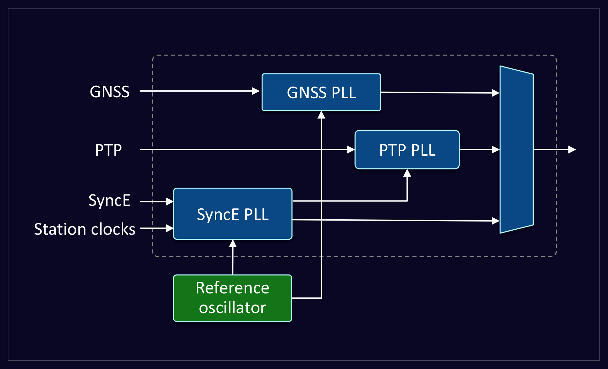
Blog: What is synchronisation holdover, and why is it important in future-proofing telecom networks?

26 January 2024

Holdover is a technique used in telecommunications to maintain accurate timing and synchronisation of equipment in the event of a temporary loss of...

synchronisation in digital communications

Blog: Synchronisation fundamentals for digital communication systems

18 July 2023

Synchronisation is fundamental to most coordinated activities, from a performance by a symphony orchestra or ballet company to digital...

Blog: Frequency reference choices for packet networks

3 May 2023

All modern transport networks are based on packet transport technologies. While synchronisation in digital networks has always been important, it has...

people in data centre

Guide: What data centre architects need to know about 5G synchronisation

16 December 2021

With the roll-out of 5G, a massive shift is happening in how telecom infrastructure is designed. With network operators wanting to create a more open...

Want to know more about our products?

Browse our product pages.

Find products using our parametric search

Talk to our sales engineers